


 text@300.cn
 400-7886-786
 Q Q
Q Q

 Add
Add


Mechanical maintenance
1. Pneumatic system
(1) The air pressure system includes a three-way combination, including solenoid valve, throttle valve, muffler, cylinder, etc. This device mainly provides air to the cutting cylinder above the spindle, the blowing of the spindle and the air cylinder in the knife storage.(note: the following is a triple combination)
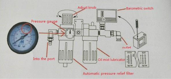
(2) On the left is the air pressure detector. When adjusting the air pressure, please gently pull up the air pressure adjustment knob.Then turn clockwise, when the pointer is above the 0. 6 reading position outside the marked barometer, the pressure will reach the desired pressure.(note: the adjustment valve rotates clockwise to increase the pressure and counterclockwise to decrease the pressure. After adjusting the pressure well, press down the adjustment knob slightly. Remember not to adjust the pressure too high, or it will cause damage to the components)
(3) On the right is the air pressure detection switch, which has been adjusted when leaving the factory. There is no need to adjust it. The position indicated by the pointer indicates that abnormal alarm will occur when the input pressure is lower than this pressure.For adjustment, use a screwdriver to turn the adjustment screw above the housing.
(4) The normal pressure must be maintained at 6-8kg/cm2. If there are too many machines in the user's factory that must use air, it is suggested to install a gas storage cylinder and a check valve beside the machine. The supply pressure must not be lower than 6kgf/cm2, otherwise the machine will stop immediately and abnormal signals will be displayed on the screen.
(5) when the air compression is not drained for a long time, the water will enter the machine along with the pipe. When the unloading filter device is filled with water, the water will be discharged automatically. When the machine stops working, the water inside can also be discharged manually.(for manual drainage, twist the bottom knob of the pressure relief filter to drain water)
(6) when the air enters the oil mist lubricator, it will take away a small amount of oil, which can lubricate all the sliding components to increase the service life of the components. The lubrication will go to the cylinder, solenoid valve, pneumatic lock knife, spindle positioning, ATC mechanism.The amount of oil in the oil cup should not be too large, lest the flow of air is too small to allow the nozzle to flow at a speed sufficient to create a vacuum, and therefore the oil cannot be drawn from the container.(use ISOVG32# compression and wear resistant hydraulic oil or VG20# spindle oil whenever possible)
2. Electromagnetic valve
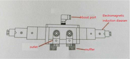
(1) The direction control valve provides the most basic circuit control method, which can make the fluid path switch or change the flow direction according to the requirements of the operation procedure, and can control the start, stop and movement direction of the actuator.
(2)The fault is usually dust: it is the main cause of the fault, usually brought in by the external inlet pipe road dirty, dust mixed with the solenoid valve induction coil, resulting in poor contact, rust or poor movement in the cylinder.Improper lubricating oil: excessive viscosity of lubricating oil caused by the use of oil, etc.
(3) In case of failure, please check whether the oil in the oil storage cup meets the requirements, and periodically check whether the air compressor of our company drains water and whether the filter element in the pressure combined pressure relief filter is blocked.
(4) Muffler: it is installed at the air outlet to reduce the noise of gas discharge.
3. Lubrication system
The triaxial guide rail and ball screw are supplied by the automatic oiler.When the automatic oiler operates, the oil is sent through the oil outlet to the Oildistributor in each shaft, which distributes the oil equally to the guide rail, ball screw and the inner bearings on both ends of the ball screw for lubrication (use ISOVG68# wear-resistant guide rail oil or the same type of guide rail oil as required).
(1) the oiler is a combination of timer, pump, level detector, oil tank and lubricating oil, which provides lubricating oil to be distributed through pipelines to Distributor (Distributor) which distributes oil evenly to the mechanical sliding surface and rotating mechanism.Pay attention to whether the oil is filled with guide rail oil in use, otherwise the oil pump cannot extract oil, which will cause damage to the load operation of the oil pump for a long time.
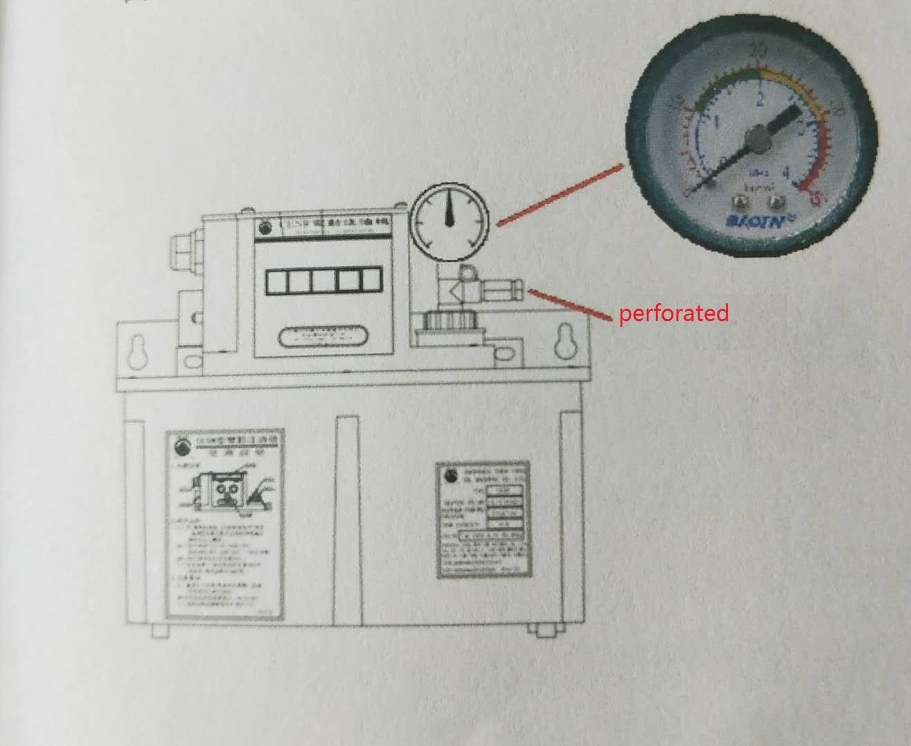
(2) when the insufficient oil in the oil tank, or the pressure cannot be detected and the oil pipe breaks, the internal detection device will output signals to the NC screen, and there will be abnormal alarm on the screen. At this time, the buzzer on the left of the oiler will emit a shrill sound, and the LUBE key on the operation panel will light up to inform the operator of abnormal alarm.
(3) when the oiler is damaged, contact the machine manufacturer to replace it; otherwise, a long period of oil shortage of the machine will lead to wear and deformation of guide rail, ball screw, etc.
(4) operation instructions of automatic oiler:
There are two timers at the front of the automatic oiler unit, which can adjust the time of operation and the time of oil output.The timer on the right is used to adjust the time of the action.The timer on the left is used to adjust the oil feeding time, which is measured in seconds.Before the machine tool leaves the factory, we have adjusted the timer on the right side to 30 minutes and on the left side to 15 seconds.The output pressure of each injection is 1.5kg/cm', these two times are the best, do not adjust arbitrarily.(note: there is an oil feed button right in front of the oiler. Pressing this button can force the oiler to act and output oil.If you think there is something wrong with the oil injector, you can press this button and see if there is any oil coming out of the transparent tubing.
4. Electrical box heat exchanger
Electrical box cooling device after long-term use, will produce a vibration, noise, or product oil, dirt, in order to maintain the electrical box cooling efficiency, must maintain a constant flow of cold air, the heat exchanger will make the air outside, through the filter into the electric box, so the mesh must be cleaned regularly every week, to avoid clogging led to the decrease of the cooling effectiveness.Although this heat exchanger, powered only by fans, has reduced the maintenance work to a minimum, so it needs regular maintenance.(note: the heat exchanger is located on the door of the electrical box)
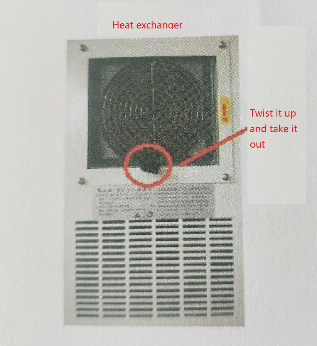
(1) turn off the power
(2) remove the filter from the heat exchanger
(3) use air gun to clean, or clean the filter with soapy water
(4) put back the filter
(5) turn on the power
5.Cutting pump/tank
(1) Check cutting fluid oil/water every week, the tank should maintain about 2/3, from the cutting fluid tank edge of the liquid level gauge can see the current cutting fluid/oil.
(2) Regularly clean the chip discharge slot. For example, the chip generated by drilling will be relatively long. Compared with the small chip generated by milling, the long chip needs to be cleaned more frequently.
(3) The cutting fluid water tank should be fixed for cleaning every period of time, the interval time depends on the use of the machine and the processing material, long time will produce dirt deposition, generally about a month to clean.
(4) The pump works in high temperature or humid environment for a long time, which is influenced by the customer's environment.Can cause pump damage or abnormal conditions.Weekly fixed inspection pump whether there is abnormal sound, water weakness, abnormal alarm overload and other conditions.
(5) Turn off the power, unplug the quick connection between the pump and the electrical box, check whether oil and water enter the pump junction box or the pipeline is damaged, pull the pump out of the water tank to check whether the filter screen is blocked or not, if so, please clean it in time.
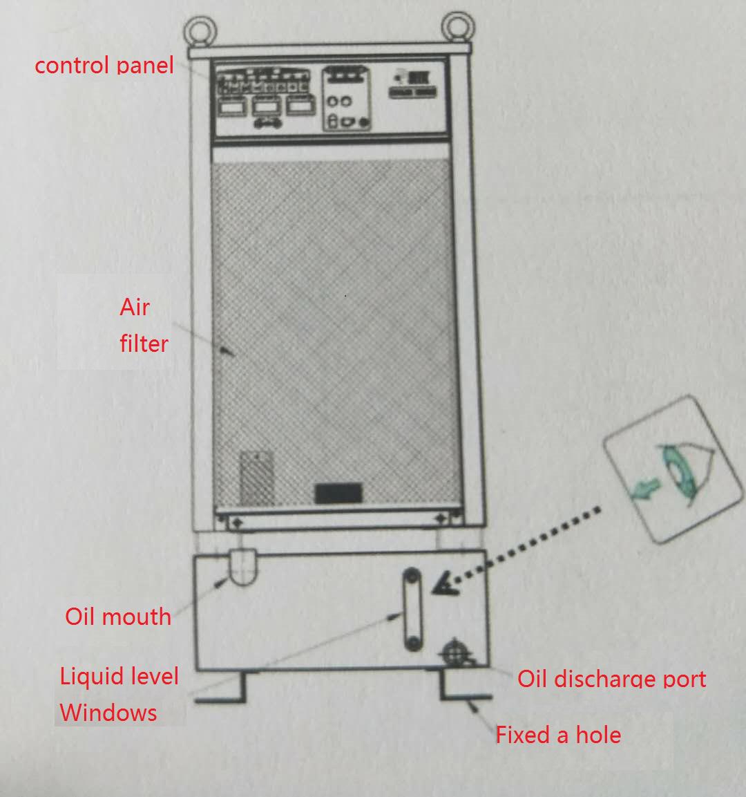
6. Spindle oil cooler
In order to maintain the cooling efficiency of the spindle oil cooler, it is necessary to maintain a fixed air flow rate. Therefore, it is very important to clean the air filter regularly. Blocked air filter will lead to insufficient air flow rate and overheating of the machine.The time of regular cleaning varies according to the processing environment of the factory. The areas with more dust need to be cleaned more frequently, generally at least once a week.(note: please use ISOVG32# wear-resistant hydraulic oil. Adding other oil will damage the main shaft.)
(1) turn off the power
(2) remove the filter from the heat exchanger
(3) use an air gun, or clean the filter with soapy water
(4) put back the filter
(5) turn on the power
7. Spindle cutting cylinder
The cutting cylinder is used to provide the main shaft to loosen the clamping power when the machine tool is equipped with a tool storehouse.When the cutting cylinder loosens the clamp, the pipe carries a small amount of oil, which lubricates all sliding components to increase their life.(note: the cutting cylinder is installed on the head of the spindle, and the head sheet metal top cover should be opened when oiling.)
(1) The amount of oil in the lubricating oil cup should not be too much each time, and the amount of oil should be kept at 2/3.(please add ISOVG32# anti-wear hydraulic oil or oil of the same type)
(2) Travel contact switch: it ensures that the clamping signal can be quickly sensed when the cutting cylinder is in action, so as to ensure that abnormal alarm will not occur when the knife is changed.
(3) the spindle cannot loosen and clamp the knife
Reason: 1. The adjusting screw at the end of the cutting cylinder is loose.2. The contact switch of the side stroke of the cutting cylinder is loose or damaged.3. Control the damage of the solenoid valve of the beating cylinder.
Countermeasures :1. Check whether there is oil on the right side of the cutting cylinder.2. Adjust the screw to the proper position.3. Manually adjust and fix the contact switch or replace the contact switch.4. Replace the solenoid valve.
(4) The device for releasing and clamping knives has been tested before leaving the factory. Users shall not unassemble or adjust the device without fault.
